Fast and light: new algorithm for partially-coherent beamline simulations at 4th generation synchrotron sources
A new algorithm to perform coherent mode decomposition of the undulator radiation has been proposed in one recent publication released in the Journal of Synchrotron Radiation by PaNOSC contributors from the European Synchrotron Radiation Facility. The research group has studied the focusing with lenses of the radiation emitted by an undulator in a fourth-generation storage ring (EBS-ESRF).
To provide some background information, the migration to fourth-generation storage-rings has significantly improved brilliance and coherence of X-ray synchrotron sources. The transverse coherent fraction of the new sources is increased by at least one order of magnitude with respect the 3rd generation sources. This has a beneficial impact for many applications requiring coherent beams. However, the diffraction effects produced by the interaction of the beam with the boundaries and distortions in the surface of the optical elements strongly affect the quality of the beam.
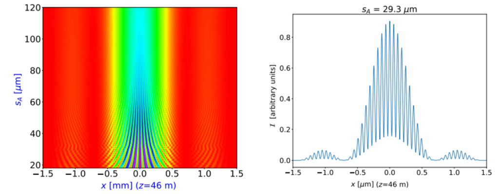
The new paper by Manuel Sanchez del Rio and colleagues proposes a new method for simulating partially coherent undulator beams, which requires a limited use of computing resources as compared to other methods (full 2D coherent mode decomposition, Monte-Carlo propagation of wavefronts from electrons entering the undulator with different initial conditions, and hybrid ray-tracing). The new algorithm reduces the dimensionality of the problem by dealing with one-dimensional (1D) wavefronts, that is by separating the horizontal and vertical directions.
In the paper it is demonstrated that in many cases of practical interest this new method can be used, and the results are comparable to the other methods, but requiring much less computer resources. The a full beamline using a partially coherent beam can be simulated in a common laptop.